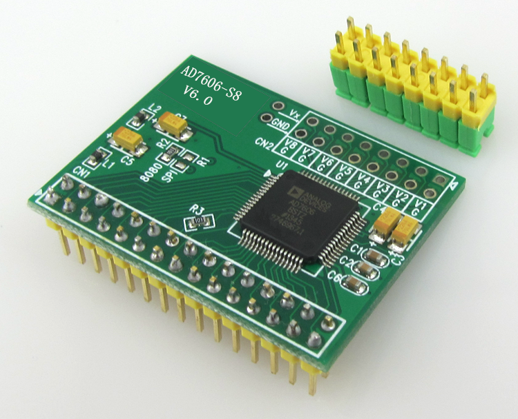
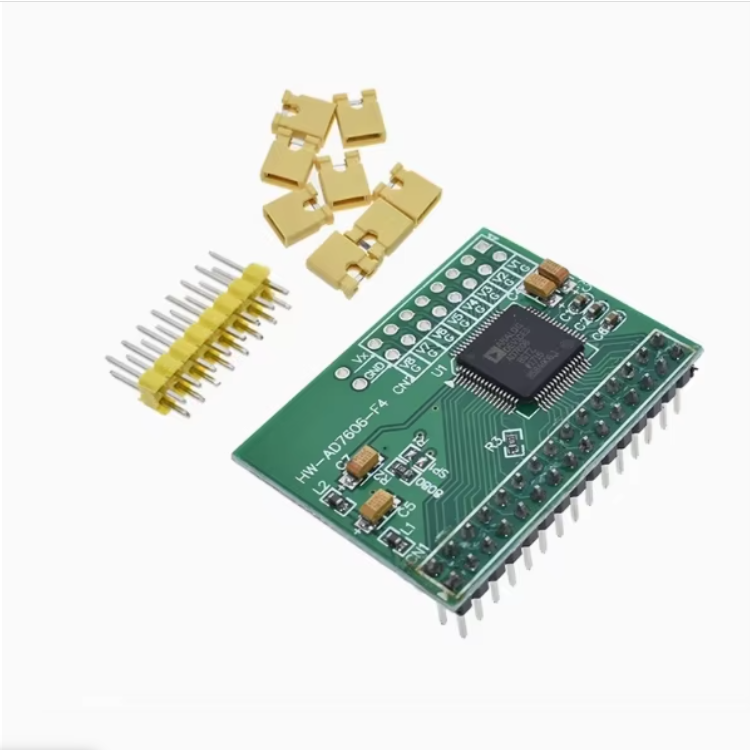
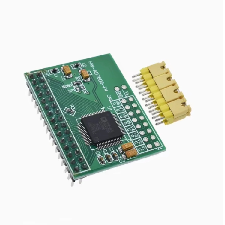
The AD7606 Data Acquisition Module Features A 16-Bit ADC With 8 Channels Of Synchronous Sampling At A Frequency Of 200KHz
The AD7606 Data Acquisition Module Features A 16-Bit ADC With 8 Channels Of Synchronous Sampling At A Frequency Of 200KHz
Couldn't load pickup availability

The AD7606 data acquisition module features a 16-bit ADC with 8 channels of synchronous sampling at a frequency of 200KHz

Product features
1. Use the AD7606 high-precision 16-bit ADC chip
2. 8-channel analog input. Impedance 1M ohms. No negative power supply is required, no front-end analog operational amplifier circuit is needed, and it can be directly connected to sensor output.
3. Input range: ± 5V, ± 10V. The range can be controlled by IO.
4. Resolution: 16 bits.
5. Maximum sampling frequency: 200Ksps. Supports 8-level oversampling Settings (which can effectively reduce jitter)6. Built-in benchmark
7. Single 5V power supply
8. SPI interface or 16-bit bus interface. The interface IO level can be 5V or 3.3V.
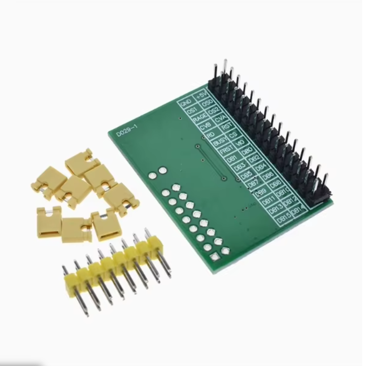
Module Pin Description
Select the oversampling mode for the combined state of OS2, OS1, and OS2.
000 indicates no oversampling, with a maximum sampling rate of 200Ksps.
001 indicates 2x oversampling, which means that two samples are collected internally by the hardware and averaged
010 indicates 4x oversampling, that is, taking the average of four samples collected internally by the hardware
011 indicates 8 times oversampling, that is, 8 samples are collected internally by the hardware and averaged
100 indicates 16 times oversampling, that is, 16 samples are collected internally by the hardware and averaged
101 indicates 32 times oversampling, that is, 32 samples are collected internally by the hardware and averaged
110 indicates 64 times oversampling, that is, taking the average of 64 samples collected internally by the hardware
The higher the oversampling ratio and the longer the ADC conversion time, the lower the maximum sampling frequency that can be obtained.
CVA,CVB: Control signals for initiating AD conversion. CVA determines channels 1 to 4, and CVB determines channels 5 to 8.
The two signals can be staggered for a short period of time. In general, CVA and CVB can be connected in parallel.
RAGE: Range selection. 0 indicates ± 5V, and 1 indicates ± 10V.
RD: Read the signal
RST: Reset Signal
BUSY: Busy signal.
CS: Chip selection signal
FRST: The indicator signal of the first channel sample
VIO: Communication interface level
DB0-DB15: Data bus