Original Genuine STC8H8K64U-45I-SOP16 1T 8051 Microprocessor Single-Chip Microcomputer
Original Genuine STC8H8K64U-45I-SOP16 1T 8051 Microprocessor Single-Chip Microcomputer
Regular price
¥1.60 CNY
Regular price
¥0.00 CNY
Sale price
¥1.60 CNY
Quantity
Couldn't load pickup availability

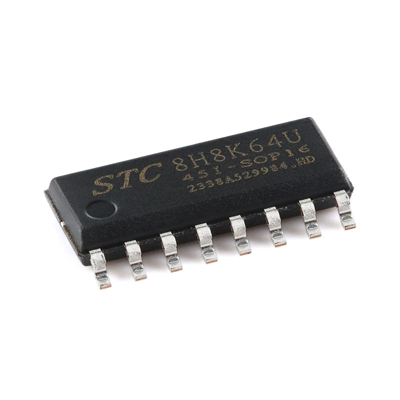
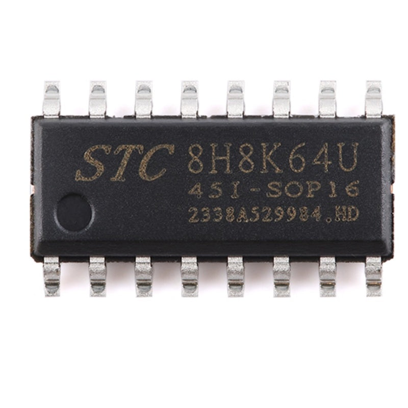
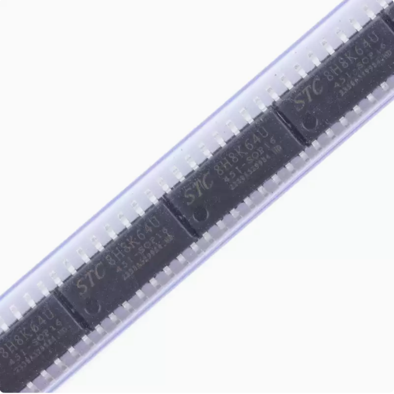
STC8H8K64U-451-SOP16
1T 8051 microprocessor single-chip microcomputer chip

Product Description
The STC8H series of single-chip microcontrollers do not require external vibration or external reset. They are the 8051 single-chip microcontrollers that aim for super strong anti-interference, ultra-low cost, high speed and low power consumption. Under the same operating frequency, the STC8H series of single-chip microcontrollers are approximately 12 times faster than the traditional 8051 (11.2 to 13.2 times faster) To execute all 111 instructions in sequence, the STC8H series microcontroller only requires 147 clocks, while the traditional 8051 needs 1,944 clocks. The STC8H series of microcontrollers is a single-clock/machine cycle (1T) microcontroller produced by STC. It is a new generation of 8051 microcontrollers featuring wide voltage, high speed, high reliability, low power consumption, strong anti-static and strong anti-interference capabilities, with super encryption. The instruction code is fully compatible with traditional 8051.
MCU internal integration and high precision clock R/C + (plus or minus 0.3%, room temperature 25 ℃), 0.88% ~ + 1.05% temperature (20 ℃ ~ + 65 ℃), 1.38% ~ + 1.42% temperature wave (- 40 ℃ ~ + 85 ℃), 3% ~ + 3% temperature wave (- 40 ℃ ~ + 125 ℃). When programming the ISP, the operating frequency can be set, which can completely eliminate the need for expensive external crystal oscillators and external reset circuits (the internal highly reliable reset circuit is integrated, and the 4-level reset threshold voltage can be selected during ISP programming).
There are three selectable clock sources inside the MCU: an internal high-precision IRC clock (which can be appropriately increased or decreased), an internal 32KHz low-speed IRC, and an external 4M to 33M crystal oscillator or external clock signal. In the user code, the clock source can be freely selected. After the clock source is chosen, it can be further divided by an 8-bit frequency divider before the clock signal is provided to the CPU and various peripheral devices (such as timers, serial ports, SPI, etc.).
The MCU offers two low-power modes :IDLE mode and STOP mode. In IDLE mode, the MCU stops providing a clock to the CPU. The CPU has no clock and stops executing instructions, but all peripheral devices are still in operation. At this time, the power consumption is approximately 1.3mA(operating frequency of 6MHz). The STOP mode is the master clock stop-vibration mode, which is the traditional power-off mode/power outage mode/shutdown mode. At this time, the CPU and all peripheral devices stop working, and the power consumption can be reduced to 0.6uA@Vcc=5.0V and 0.4uA@Vcc=3.3V.
The MCU offers a rich array of digital peripheral interfaces (serial port, timer, advanced PWM, as well as I²C, SPI, USB) and analog peripherals (ultra-high-speed ADC, comparator), which can meet the design requirements of a wide range of users.
The STC8H series of single-chip microcontrollers integrate enhanced dual data Pointers internally. Through program control, the functions of automatic increment or decrement of data Pointers and automatic switching between two groups of data Pointers can be achieved.
Product features
Core
- The ultra-high-speed 8051 core (1T) is approximately 12 times faster than the traditional 8051
- The instruction code is fully compatible with traditional 8051
- 22 interrupt sources, with 4 levels of interrupt priority
- Supports online simulation
Working voltage
- 1.9V to 5.5V
Working temperature
- -20℃ to 65℃(Internal high-speed IRC temperature: -0.76% to +0.98%)
- -40℃ to 85℃(internal high-speed IRC temperature drift ±1.3%)
- -40℃ to 125℃(Internal high-speed IRC temperature drift +3%. When the temperature exceeds 85℃, please use an external high-temperature resistant crystal oscillator of 24MHz or less.)
Flash memory
- Up to 64K bytes of FLASH program memory (ROM) for storing user code
- Supports user configuration of EEPROM size, 512-byte single-page erasure, and the erase and write cycles can reach over 100,000 times
- Supports updating user applications in System Programming Mode (ISP) without the need for a dedicated programmer
- It supports single-chip simulation without the need for a dedicated simulator, and there is no limit to the number of theoretical breakpoints
Clock control
- Internal high-precision IRC(45MHz and below, selected or manually entered during ISP programming, and can also be divided by user software to operate at lower frequencies, such as 100KHz)
- Error ±0.3%(at room temperature of 25℃)
- Temperature drift: -0.76% to +0.98% (temperature range: -20℃ to 65℃, with 25℃ as the center point)
- Temperature drift: -1.35% to +1.30% (temperature range: -40℃ to 85℃, with 25℃ as the center point)
- Temperature drift of -3% to +3% (temperature range, -40℃ to 125℃, with 42.5℃ as the center point)
- Internal 32KHz low-speed IRC(with relatively large error)
- External crystal oscillator (45MHz and below) and external clock
- Users can freely choose from the above three clock sources
Reset
- Hardware reset
- When powered on and reset, the measured voltage value is 1.69V to 1.82V. (Effective when the low-voltage reset function is not enabled on the chip)
- The power-on reset voltage is a voltage range composed of an upper limit voltage and a lower limit voltage. When the working voltage drops from 5V/3.3V to the lower limit threshold voltage for power-on reset, the chip is in the reset state; when the voltage rises from 0V to the upper limit threshold voltage for power-on reset, the chip is out of the reset state.
- Reset pin reset. By default, P5.4 is the I/O port at the factory. When the ISP downloads, the P5.4 pin can be set as the reset pin (Note: When P5.4 pin is set as the reset pin, the reset level is low).
- Watchdog overflow reset
- Low-voltage detection reset, providing 4 levels of low-voltage detection voltages :1.9V, 2.3V, 2.8V, and 3.7V.
- Each level of low-voltage detection voltage is a voltage range composed of an upper limit voltage and a lower limit voltage. When the working voltage drops from 5V/3.3V to the lower limit threshold voltage of low-voltage detection, the low-voltage detection takes effect; when the voltage rises from 0V to the upper limit threshold voltage of low-voltage detection, the low-voltage detection takes effect.
- Software reset
- Write the reset trigger register in software mode
Products photography