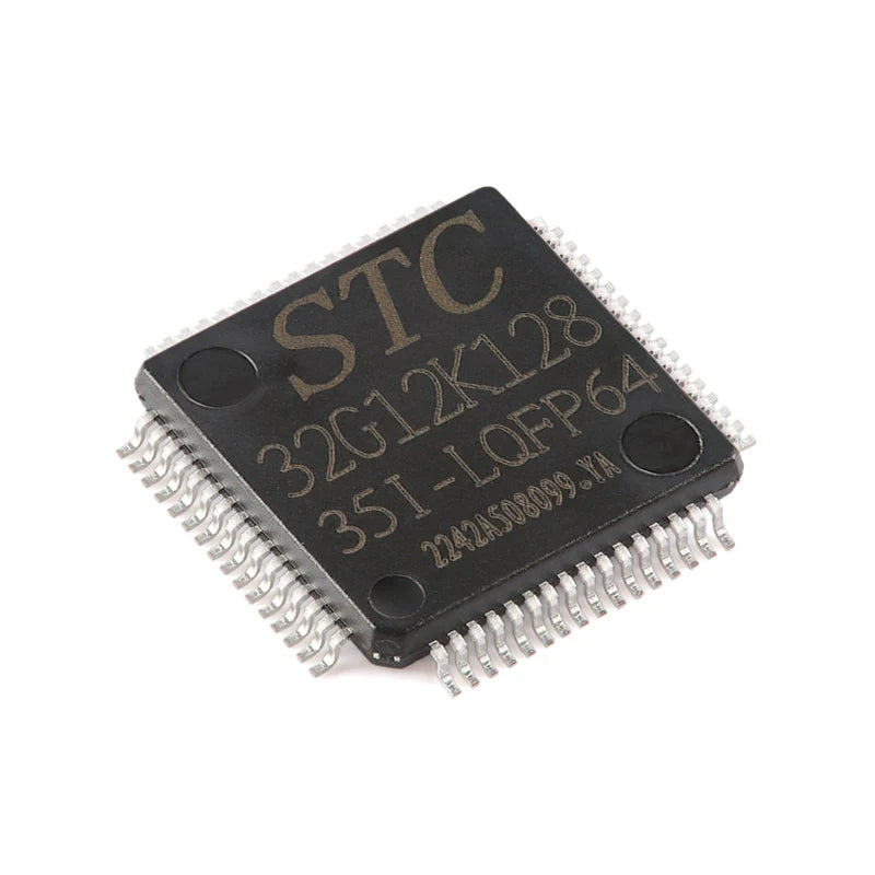
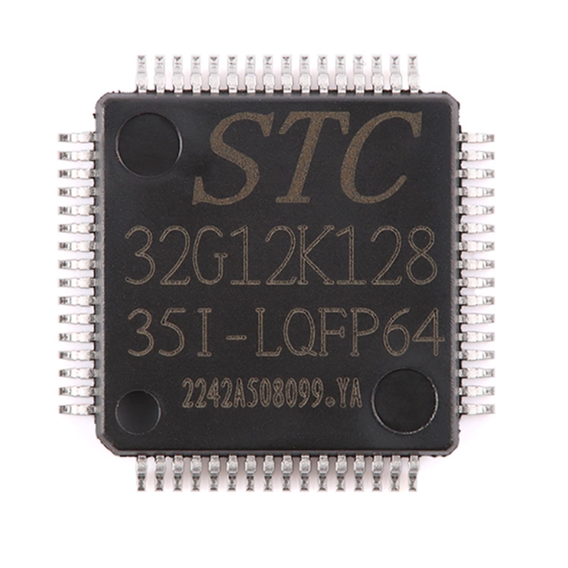
Brand-New Original STC32G12K128-35I-LQFP64 32-Bit 8051 Core Single-Chip Microcomputer Chip
Brand-New Original STC32G12K128-35I-LQFP64 32-Bit 8051 Core Single-Chip Microcomputer Chip
Regular price
¥3.45 CNY
Regular price
¥0.00 CNY
Sale price
¥3.45 CNY
Quantity
Couldn't load pickup availability

STC32G12K128-351-L0FP64
32-bit 8051 core single-chip microcomputer chip

Product Description
The STC32G series of single-chip microcontrollers do not require external vibration or external reset. They are 32-bit 8051 single-chip microcontrollers that aim for super strong anti-interference, ultra-low cost, high speed and low power consumption. Under the same operating frequency, the STC32G series of single-chip microcontrollers are approximately 70 times faster than the traditional 8051.
The STC32G series of microcontrollers is a single-clock (1T) microcontroller produced by STC. It is a new generation of 32-bit 8051 microcontrollers featuring wide voltage, high speed, high reliability, low power consumption, strong anti-static and strong anti-interference capabilities, with super encryption.
MCU internal integration and high precision clock R/C (+ 0.3%, + 25 ℃) under normal temperature, temperature - 1.38% ~ + 1.42% floating (- 40 ℃ ~ + 85 ℃), 0.88% ~ + 1.05% temperature wave (- 20 ℃ ~ + 65 ℃). When programming the ISP, a wide range of 4MHz to 33MHz can be set, which can completely eliminate the need for expensive external vibration and external reset circuits (the internal highly reliable reset circuit is integrated, and the 4-level reset gate voltage is selectable during ISP programming).
There are four optional clock sources inside the MCU: an internal high-precision IRC clock (the frequency can be adjusted during ISP programming), an internal 32KHz low-speed IRC, an external 4M to 33M pin oscillator or external clock signal, and an internal PLL output clock. In the user code, the clock source can be freely selected. After the clock source is chosen, it can be further divided by an 8-bit frequency divider before the clock signal is provided to the CPU and various peripheral devices (such as timers, serial ports, SPI, etc.).
The MCU offers two low-power modes: IDLE mode and STOP mode. In IDLE mode, the MCU stops providing a clock to the CPU. The CPU has no clock and stops executing instructions, but all peripheral devices are still in operation. At this time, the power consumption is approximately 1.3mA(operating frequency of 6MHz). The STOP mode, also known as the master clock stop-vibration mode, is the traditional power-off mode/power outage mode/shutdown mode. At this time, the CPU and all peripheral devices stop working, and the power consumption can be reduced to below 1uA.
The MCU offers a rich array of digital peripherals (4 serial ports, 5 timers, 2 sets of 16-bit advanced PWM timers capable of outperforming complementary/symmetric/dead zone control signals for three-phase motor control, as well as I²C, SPI, USB, CAN, LIN) interfaces and analog peripherals (ultra-high-speed 12-bit ADC, comparator) It can meet the design requirements of a wide range of users.
The STC32G series microcontrollers have 268 powerful instructions, including 32-bit addition and subtraction instructions and 16-bit multiplication and division instructions. The hardware has been expanded with a 32-bit hardware multiplication and division unit MDU32(including 32-bit division by 32-bit and 32-bit flexible division by 32-bit).
The STC32G series of microcontrollers integrates enhanced dual data Pointers internally. Through program control, the functions of automatic increment or decrement of data Pointers and automatic switching between two groups of data Pointers can be achieved.
Product features
Core
- Super Ultra 32-bit 8051 core (IT). It is over 70 times faster than the traditional 8051
- 49 interrupt sources, with a priority of 4 levels
- Supports online simulation
Working voltage
- 1.9V to 5.5V (When the working temperature is below -40℃, the working voltage shall not be lower than 3.0V)
Working temperature
- -40℃ to 8S℃(Internal high-speed IRC(36MHz or below) and external vibration can be used)
<-40℃ to 125℃(When the temperature exceeds 85℃, please use external high-temperature resistant vibration products and keep the working frequency below 24MHz)
Flash storage crash
- Up to 128K bytes of FLASH program memory (ROM), used for storing user code
- Supports user configuration of EEPROM size, with a single-page erasure of 512 bytes, and the erasure and write cycles can reach over 100,000 times
- Supports direct download via hardware USB and ordinary serial port download
- Supports real-time simulation of hardware SWD. P3.0 / P3.1
SRAM, totaling 12K bytes
-4K bytes of internal SRAM(edata
-8K bytes of internal extended RAM(internal xdata)
Clock control
- Internal high-precision IRC (can be adjusted up and down during ISP programming)
◆ Error ±0.3%(at room temperature of 25℃)
◆ -1.35% - +1.30% temperature drift (full temperature range, -40℃ - 85℃)
◆ -0.76% - +0.98% temperature drift (temperature range, -20℃ - 65℃)
- Internal 32KHz low-speed IRC(with relatively large error)
- External vibration (4MHz-33MHz) and external clock, with a dedicated external clock to interfere with the internal circuit, can be started by software
- Internal PLL output clock (Note :PLL, with an output of 96MHz/144MHz, can independently serve as the clock source for high-speed PWM and high-speed SPI.) Users can freely choose from the above four clock sources
Reset
- Hardware reset
◆ Power-on reset, the reset voltage value is 1.7V to 1.9V. (Effective when the low-voltage reset function is not enabled on the chip)
◆ Reset pin reset. By default, P5.4 is the I/O port at the factory. When the ISP downloads, the P5.4 pin can be set as the reset pin. (Note: When P5.4 pin is set as the reset pin, the reset level is low.)
◆ Watchdog overflow reset
◆ Low-voltage detection reset. Four levels of low-voltage detection voltages are provided :2.0V, 2.4V, 2.7V, and 3.0V.
- Software reset
◆ Write the reset trigger register in software mode
-
Analog peripheral
- ADC: Ultra-high-speed ADC, supporting 12-bit high-precision 15-channel (Channel 0 to Channel 14) analog-to-digital conversion. Channel 15 of the ADC is used to test the internal reference voltage (the internal reference voltage is adjusted to 1.19V at the factory, with an error of ±1%).
- Comparator: A set of comparators
GPIO
- All GPIOs support the following four modes: quasi-bidirectional port mode, strong push-pull output mode, open-drain output mode, and high-impedance input mode
- Except for P3.0 and P3.1, all other IO ports are in a high-impedance input state after power-on. Users must set the IO port mode before using the IO ports
- In addition, each I/O can independently enable the internal 4K pull-up resistor
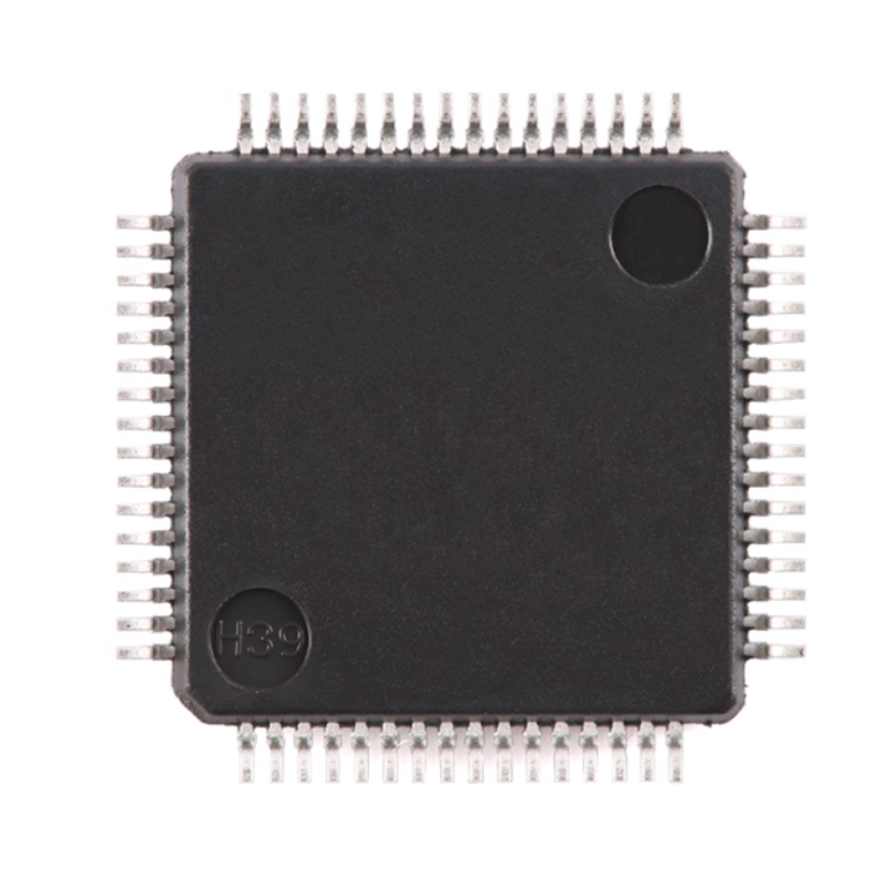
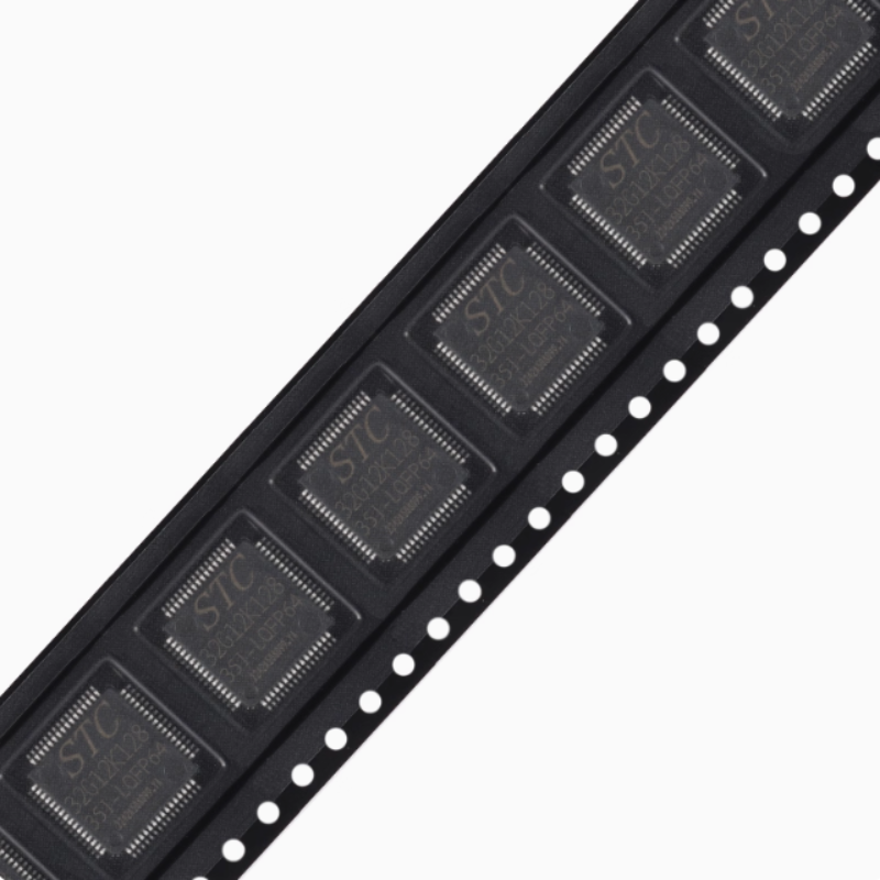
Products photography